

Hydraulic shock and sway suppressors (snubbers)
Application
| Performance
| Construction
Features | Models
available
| Standard
Settings and Test Values at Room Temperature
Allowable Loads
| Technical
Data
 |
||||||||||
 |
||||||||||
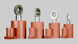
Hydraulic shock suppressors Fig. 202 A
Standard
settings and test values at room temperature
in accordance with KTA 3205.3 and VGB-R510L:
| Starting resistance: | max 2 % of the nominal load (or 300 N for snubbers with a nom. load less or equal 15 kN) |
| Frictional resistance: | max 2 % of the nominal load (or 200 N for snubbers with a nom. load less or equal 10 kN) |
| Response velocity: | 3 – 6 mm/s |
| Bypass velocity: | 0.2 - 2.0 mm/s |
| Piston rod travel Sa: | > 0.5 mm (lost motion) |
| Piston rod travel Sb: | < amount + / - 0.02 nominal travel (peak to peak) |
| Temperature: | max. operating temperature 80° C (short-time operating temperature for a duration at max. 3 hours 150° C) |
| Deflections: | max. deflection cross to the bolt
axis: ± 70° max. deflection in the bolt axis: min. ± 5° |
| Fig. 200A, 200B, 202 |
Fig. 201A, 201B, 203 ( with extension ) |
||
| Opt. 0: | 1 snubber body with 2 rod
eyes |
Opt. 0: | 1 snubber body with 2 rod
eyes 1 extension piece |
| Opt. 1: | 1 snubber body with 2 rod eyes 1 rear bracket EHS 14 S at the fixpoint |
Opt. 1: | 1 snubber body with 2 rod eyes 1 rear bracket EHS 14 S at the fixpoint 1 extension piece |
| Opt. 2: | 1 snubber body with 2 rod eyes 2 rear brackets, EHS 14 S |
Opt. 2: | 1 snubber body with 2 rod eyes 2 rear brackets, EHS 14 S 1 extension piece |
| Opt. 3: | 1 snubber body with 2 rod eyes 1 rear bracket EHS 14 S at the fixpoint 1 special dynamic pipe clamp |
Opt. 3: | 1 snubber body with 2 rod eyes 1 rear bracket EHS 14 S at the fixpoint 1 extension piece 1 special dynamic pipe clamp |
![]()